Wings 3D/Tutorials/Making pipe fittings with Wings/A different approach
There is at least one other method of making pipe fittings available on the internet, and the methods posted there make a wider variety of fittings. This is another approach.
Okay, we are going to make three different types of pipe fittings with this technique.
A 90% elbow joint.
A pipe "Tee"
And a four way fitting.
The "Tee" is made from the elbow joint, and the four way is made from the "Tee".
STEP 1
[edit | edit source]Start with a basic cylinder. Select it with the body tool (the all red pyramid in the group of four at the top of the W3D screen), it should all turn red, like the image in Step 2.
STEPs 2 & 3: ROTATE
[edit | edit source]Right click to bring up the body menu. Select ROTATE. It will ask you what axis you want to rotate about. Select the "X" axis. BUT DO NOT MOVE YOUR MOUSE. Instead, hit the <tab> key. A menu will pop up asking you for a numeric value for the rotation in degrees. Input 90. The cylinder should now be laying on its side. DON'T hit your space bar to deselect it, instead, right click again and select rotate once more. This time pick the "Y" axis. Again, DON'T move the mouse. Hit <tab> and put in the value of -45 (minus 45, not plus) Make sure you are in orthographic view (that is the rightmost of the two pyramids in the upper left corner of your screen). The top image is an orthographic view, which means you are looking at it from a 45 degree angle to start, so when you do the second rotation, it appears sideways on to your point of view (POV).
STEP 4
[edit | edit source]Use your mouse to drag a box around the vertices at the right edge of the cylinder. (Alternatively, you could also use face select and use flatten in the face menu) You should now have all the vertices at one end selected. Leaving them selected, right click to bring up the vertices menu and choose FLATTEN > X. This will make all those vertices flatten into a plane perpendicular to the X axis. If you hit your <x> key so you are looking down the "X" axis, you should see an oval shape.
 File:Step004.jpgFile:Step005.jpg
STEP 5
[edit | edit source]Hit the spacebar to deselect the vertices (if you used face select, just leave things as they are) Go into face mode and select the face created by the vertices you just flattened. Right click to bring up the face menu. Do EXTRACT REGION > X to make a copy of just that face. Drag it away from the cylinder. Hit your spacebar to deselect everything.
STEP 6
[edit | edit source]Now go into body mode and select the now deformed cylinder. Hit <backspace> to delete it.
File:Step008a.jpg File:Step009.jpg
STEP 7
[edit | edit source]Select the region you just extracted. On the menu across the top of the screen click on TOOLS > CENTER > ALL. The oval shape should now be centered at the origin of the workplane.
STEP 8: MORE ROTATION
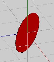
[edit | edit source]With it still selected, right click and select ROTATE > X. Don't move the mouse. Hit <tab> and enter 90 in the pop up box. Leave the oval selected. You will get this:
Below is the view looking straight down the "X" axis.
STEP 8
[edit | edit source]Right click and pick rotate again. This time choose "Y". Don't use the mouse. Hit <tab> and enter the value 45. (we are going a POSITIVE 45 degrees this time...) Your oval will rotate to a 45 degree angle.
TWO VIEWS: ORTHO AND STRAIGHT DOWN THE "X" AXIS AFTER ROTATION.
STEP 9
[edit | edit source]Go into face mode and select ONE SIDE ONLY of the oval. Right click. Do EXTRUDE REGION > X. Don't move the mouse. <tab> and enter the value 3.
STEP 10
[edit | edit source]The face you just extruded should still be selected. Right click. Select FLATTEN > X. Now you have a cylinder that is flat on one face and at 45 degrees on the other.
You now have one half of a 90-degree pipe elbow with one end mitered at a 45-degree angle.
STEP 11
[edit | edit source]Hit space to deselect everything. In face mode, rotate your model and select the 45 degree angled face.
Do TOOLS > VIRTUAL MIRROR > CREATE.
Now do TOOLS > VIRTUAL MIRROR > FREEZE. Now you have a 90 degree elbow! All you have to do is make it hollow, which we do in the next step.
STEP 12
[edit | edit source]In face mode, select the two "ends" of your elbow and right click. Select INTRUDE from the menu. Move your mouse until you achieve your desired degree of wall thickness and left click. You will now have a completed 90 degree pipe elbow. This is the foundation for the pipe "Tee" and the four way connection.
In the next steps, we will make the pipe "Tee", which involves cutting away portions of an "un-intruded" 90 degree elbow and then doing another VIRTUAL MIRROR/FREEZE MIRROR. We will also do a four way connection by cutting up a pipe "Tee" and re-joining it.


