Circuit Idea/Deborah Chung's "Apparent Negative Resistance"
Circuit idea: There is not any connection between this arrangement and the negative resistance phenomenon.

Some history
[edit | edit source]In July 1998, Deborah Chung and Shoukai Wang of the University of Buffalo presented the results of an experiment that showed an apparent absolute negative resistance in bare carbon fibers held together by pressure.[1]
In the experiment, two bundles of carbon fibers are arranged in a cross shape, with the ends of each bundle shorted with copper foil and silver paint (at A, B, C, and D in the image). A current is driven through one branch, and a voltage is measured across the other branch. In the paper, the voltage divided by current is referred to as an "apparent resistance" (a real electrical resistance requires both the current and voltage to be measured at the same points.)
The paper describes how the apparent contact resistance of the interface changes from positive to negative when the fibers are compressed. The current-voltage characteristic of the measured "negative resistance" is then a straight line of negative slope through the origin. The apparent negative resistance was also observed in metal wires (silver-coated copper), but was not observed for a single fiber crossing another single fiber. The paper claims that this phenomenon is useful because the forward flow and backflow of electrons in the same piece of material can be reproducibly controlled by external forces.
Presenting the carbon fiber network as a bridge circuit
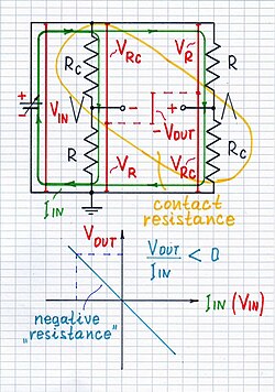
[edit | edit source]If we scrutinize this exotic carbon fiber arrangement, we will reralize it acts as some kind of bridge circuit formed by two kinds of resistances - steady carbon fiber resistances R and varying contact resistances Rc. In some way (for now unrecognized), it turned out they were connected in the opposite bridge legs. By the way, a long time ago I was impressed by this remarkable feature of the bridge circuit - to reverse the output voltage. It can do that because the output voltage is a differential quantity. It is "flying"; it is the difference between the two grounded voltages - VR and VRc. Depending on the proportion between R and Rc, this difference may be zero (R = Rc), positive (R > Rc) or negative (R < Rc). And, if we assume the current IIN is the input quantity and the voltage VOUT is the output quantity, we may think of this device as a zero, a positive or... a "negative" transresistance converter:) But this is not a negative resistance; this is not even a resistance; it is the more abstract transresistance.
 |
 |

|
Discovering the carbon fiber network
[edit | edit source]No pressure is applied
[edit | edit source]

Well, let's look at Fig. 2 and begin thinking... The two laminae are connected to each other by great number of contact resistances Rc; you may think of the central cross area as a kind of cube. The current flows from the top lamina that is positive to the bottom lamina that is negative. So, the upper point B is positive and the lower point D is negative; the output voltage VOUT has a positive polarity as it is shown on the picture. The "resistance" is positive: R = VOUT/IIN > 0.
A big pressure is applied
[edit | edit source]

Now, let's look at Fig. 3 and continue thinking together. Now, a big pressure is applied; so, the two laminae are connected to each other by great number of zero contact resistances. In this case, the central cross area is a flat grid. The current goes into the left side of the grid, turns to the bottom and goes out from the bottom side of the grid. In this situation, the point D stays closer to the positive terminal of the input voltage source and the point B stays closer to the negative terminal. So, the point D is more positive than the point D and the output voltage VOUT has a negative polarity as shown on the right picture. As a result, like Professor Chung, we might draw a wrong conclusion that the "resistance" is "negative": R = -VOUT/IIN < 0 and to begin making a stir.
A moderate pressure is applied
[edit | edit source]Finally, we may suppose there is some middle pressure between the extreme limits when the output voltage VOUT is zero. The "resistance" is zero as well: R = VOUT/IIN = 0.
Conclusions
[edit | edit source]Then, what has Professor Deborah Chung actually observed? What has she done? Let's try to answer...
It is clear she has made some kind of exotic bridge circuit depending on applied pressure. Indeed, this carbon fiber arrangement can serve as an odd voltage-to-voltage converter, a current-to-voltage converter or as a (poor) pressure-to-voltage converter (a pressure sensor). But IMO, there are no any benefits of using it; contrary, there are many losses... Only see in Google how many people are involved in this useless discussion and how much efforts, time and money are wasted... It is a pity to see how people relying more on "reputable" sources than on their own human common sense are misleaded!
There is not any connection between this experiment and the negative resistance phenomenon.
There is not any apparent, absolute, differential or even dynamic resistance in this arrangement; there is only ordinary, bare, "19th century" ohmic resistance.
Chung's carbon fiber network behaves actually as an odd bridge circuit depending on the applied pressure (like the ordinary tensometric bridge circuit).
It seems Chung's experiment is the greatest misconception in the area of negative resistance phenomena.
References
[edit | edit source]- ↑ Apparent negative electrical resistance in carbon fiber composites — Shoukai Wang, D.D.L. Chung — Composite Materials Research Laboratory, State University of New York at Buffalo — Received 8 April 1998; accepted 31 March 1999
