Engineering Acoustics/Electro-Mechanical Analogies
Why Circuit Analogs?
[edit | edit source]Acoustic devices are often combinations of mechanical and electrical elements. A common example of this would be a loudspeaker connected to a power source. It is useful in engineering applications to model the entire system with one method. This is the reason for using a circuit analogy in a vibrating mechanical system. The same analytic method can be applied to Electro-Acoustic Analogies.
How Electro-Mechanical Analogies Work
[edit | edit source]An electrical circuit is described in terms of its potential (voltage) and flux (current). To construct a circuit analog of a mechanical system we define flux and potential for the system. This leads to two separate analog systems. The Impedance Analog denotes the force acting on an element as the potential and the velocity of the element as the flux. The Mobility Analog equates flux with the force and velocity with potential.
| Mechanical | Electrical Equivalent | |
|---|---|---|
| Impedance Analog | ||
| Potential: | Force | Voltage |
| Flux: | Velocity | Current |
| Mobility Analog | ||
| Potential: | Velocity | Voltage |
| Flux: | Force | Current |
For many, the mobility analog is considered easier for a mechanical system. It is more intuitive for force to flow as a current and for objects oscillating the same frequency to be wired in parallel. However, either method will yield equivalent results and can also be translated using the dual (dot) method.
The Basic Elements of an Oscillating Mechanical System
[edit | edit source]The Mechanical Spring:
The ideal spring is considered to be operating within its elastic limit, so the behavior can be modeled with Hooke's Law. It is also assumed to be massless and have no damping effects.
The Mechanical Mass
In a vibrating system, a mass element opposes acceleration. From Newton's Second Law:
The Mechanical Resistance
The dashpot is an ideal viscous damper which opposes velocity.
Ideal Generators
The two ideal generators which can drive any system are an ideal velocity and ideal force generator. The ideal velocity generator can be denoted by a drawing of a crank or simply by declaring , and the ideal force generator can be drawn with an arrow or by declaring
Simple Damped Mechanical Oscillators
In the following sections we will consider this simple mechanical system as a mobility and impedance analog. It can be driven either by an ideal force or an ideal velocity generator, and we will consider simple harmonic motion. The m in the subscript denotes a mechanical system, which is currently redundant, but can be useful when combining mechanical and acoustic systems.
The Impedance Analog
[edit | edit source]The Mechanical Spring
In a spring, force is related to the displacement from equilibrium. By Hooke's Law,
The equivalent behaviour in a circuit is a capacitor:
The Mechanical Mass
The force on a mass is related to the acceleration (change in velocity). The behaviour, by Newton's Second Law, is:
The equivalent behaviour in a circuit is an inductor:
The Mechanical Resistance
For a viscous damper, the force is directly related to the velocity
The equivalent is a simple resistor of value
Example:
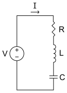
Thus the simple mechanical oscillator in the previous section becomes a series RCL Circuit:
The current through all three elements is equal (they are at the same velocity) and that the sum of the potential drops across each element will equal the potential at the generator (the driving force). The ideal voltage generator depicted here would be equivalent to an ideal force generator.
IMPORTANT NOTE: The velocity measured for the spring and dashpot is the relative velocity ( velocity of one end minus the velocity of the other end). The velocity of the mass, however, is the absolute velocity.
Impedances:
| Element | Impedance | |
|---|---|---|
| Spring | Capacitor | |
| Mass | Inductor | |
| Dashpot | Resistor |
The Mobility Analog
[edit | edit source]Like the Impedance Analog above, the equivalent elements can be found by comparing their fundamental equations with the equations of circuit elements. However, since circuit equations usually define voltage in terms of current, in this case the analogy would be an expression of velocity in terms of force, which is the opposite of convention. However, this can be solved with simple algebraic manipulation.
The Mechanical Spring
The equivalent behavior for this circuit is the behavior of an inductor.
The Mechanical Mass
Similar to the spring element, if we take the general equation for a capacitor and differentiate,
The Mechanical Resistance
Since the relation between force and velocity is proportionate, the only difference is that the mechanical resistance becomes inverted:
Example:
The simple mechanical oscillator drawn above would become a parallel RLC Circuit. The potential across each element is the same because they are each operating at the same velocity. This is often the more intuitive of the two analogy methods to use, because you can visualize force "flowing" like a flux through your system. The ideal voltage generator in this drawing would correspond to an ideal velocity generator.
IMPORTANT NOTE: Since the measure of the velocity of a mass is absolute, a capacitor in this analogy must always have one terminal grounded. A capacitor with both terminals at a potential other than ground may be realized physically as an inverter, which completes all elements of this analogy.
Impedances:
| Element | Impedance | |
|---|---|---|
| Spring | Inductor | |
| Mass | Capacitor | |
| Dashpot | Resistor |


