Engineering Acoustics/Piezoelectric Acoustic Sensor
Introduction
[edit | edit source]Piezoelectric Acoustic Wave technologies have been used for over 60 years. They have many applications for pressure, chemical concentration, temperature or mass sensors. Their detection mechanism is based on acoustic wave propagation. An acoustic wave is excited and propagates through or on the surface of the material. Changes to the characteristics of the propagation path affect the velocity and/or amplitude of the wave. Changes in velocity/amplitude can be monitored by measuring the natural frequency or phase characteristics of the sensor, which can then be correlated to the corresponding physical or chemical quantity being measured. [1] Acoustic waves sensors use piezoelectric materials to generate and detect acoustic waves. Piezoelectric materials provide the transduction between electrical and mechanical response conversion of electrical signal into mechanical acoustic waves and vice versa. Conventional piezoelectric materials includes quartz, LiNbO3, AlN and LiTaO3.
Acoustic Wave Propagation Modes
[edit | edit source]Piezoelectric acoustic wave devices are described by the mode of wave propagation through or on a piezoelectric substrate. If the wave propagates on the surface of the substrate, it is known as a surface wave; and if wave propagating through the substrate is called a bulk wave.
Mechanical waves in sensor devices
[edit | edit source]Mechanical waves for sensor applications are of two different types: shear waves and compressional waves. Shear waves (also called S wave) have particle displacements that are normal to the direction of wave propagation, as for surface water waves. Compressional waves (also called P wave) are waves in which the displacement of the particle is along the same direction as the propagation direction of the wave[2].
Acoustic Wave Technology
[edit | edit source]Surface acoustic wave (SAW) and bulk acoustic wave (BAW) are two most commonly used technologies in sensor applications.
Surface Acoustic Wave
[edit | edit source]The operation frequency of the SAW device ranges from the MHz to GHz range, mainly depending on the interdigital transducer’s design and piezoelectric material[3]:
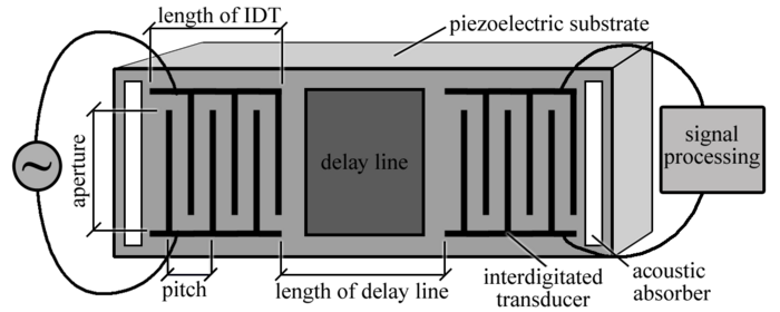
where is Rayleigh wave velocity determined by material properties and λ is the wavelength defined as the periodicity of the IDT. The figure below is SAW delay line configuration, which consists of two IDTs, one of them acting as the transmitter to generate acoustic waves, and the other as a receiver, the path between the IDTs is known as the delay-line. When an electric signal is applied on the interdigitated electrodes (IDT) with alternate polarity, as shown in Figure, an alternating regions of tensile and compressive strain between two fingers of the electrodes due to piezoelectric effect of material. A mechanical wave is generated at the surface. The mechanical wave propagates in both directions from the input IDT, only half of the energy of the mechanical wave propagates across the delay line in the direction of the output IDT. [4] The delay-line is sensing area, usually, the sensor material is deposited on the delay-line for chemical sensor to absorb the target analytics.

The animation below is time-domain simulation for the 2D structure of SAW device using COMSOL. The x,y-axis represent the position of model. The small rectangles on top are electrodes.
Sensor Response
[edit | edit source]The surface acoustic wave is sensitive to changes in the surface properties of the medium in the delay-line, these changes modulate the velocity and amplitude of the wave.
The surface wave velocity can be perturbed by various factors, each of which represents a possible sensor response[5]
- where is unperturbed wave velocity, is mass, is temperature and c is stiffness.
Therefore, this kind of devices can be used in mass, pressure and temperature sensing applications.
Mass sensor
[edit | edit source]One of the most used surface acoustic waves (SAW) sensor are mass sensor.
Example of application: Gas Sensor, Bio-sensor
The sensor material is deposited along the propagation path between the two IDTs. After exposure to a target analytes (e.g. target gas), the active sensing material of the sensor adsorbs the analytes molecules only, which causes the mass of the sensing material to increase and the surface acoustic wave speed to decrease on the propagation path due to mass loading. This causes a change in the delay time[6],
where is the length of propagation path. By tracking the delay time change at the receiver IDT, one can infer the concentration of the target analyte.
Equivalent circuit
[edit | edit source]Mason’s Crossed-Field model was used to develop the equivalent electrical circuit for an one period of IDT fingers[7]. Frequency dependent resistance blocks were used. Resistance is minimum for the center frequency of the SAW device, and very high for remaining frequencies. Thus, the input energy propagates only at the frequencies in near the resonant frequency. The equivalent circuit below is implemented using ADS.
 |
| Mason’s equivalent circuit of one period IDT in surface acoustic wave delayline devices |
Bulk Acoustic Wave
[edit | edit source]A bulk acoustic wave is a wave that travels through a piezoelectric material, as in a quartz delay line. It is also known as a volume acoustic wave. In some materials, the wave velocity is greater for bulk acoustic waves than surface acoustic wave because SAW is composed of a longitudinal and a shear wave. The wave velocity is lower than both of them. Bulk acoustic waves contain either longitudinal or shear waves only, and thus propagate faster.
Quartz Crystal Microbalance (QCM) technology
[edit | edit source]QCM is the oldest and simplest acoustic wave device for mass sensors. It consists of a thin disk of AT-cut quartz with parallel circular electrodes patterned on both sides. The application of a voltage between these electrodes results in a shear deformation of the crystal[8].

 |
| QCM principle |
The working principle is based on mass-loading, which is similar to SAW sensor.
Bulk adsorption of target analyte onto the coated crystal causes an increase in effective mass, which reduces the resonant frequency of the crystal, in direct proportion to the concentration of target analyte. For ideal sensing material, this sorption process is fully reversible with no long-term drift effect, giving a highly reliable and repeatable measurement[9].
The relation between the frequency shift and the mass-loading can be obtained from a model developed by Prof. Dr. Günter Sauerbrey from Tiefenort, Germany, in 1959:
- - resonant frequency depends on the wave velocity (v) and the piezoelectric material thickness,
- - frequency change
- - mass change
- - active area
- - density of piezoelectric material
- -shear modulus of piezoelectric material
Thin-film Bulk Acoustic Resonator (FBAR) technology
[edit | edit source]FBAR is special case of QCM with piezoelectric films thicknesses ranging from only several micrometers down to tenth of micrometers using MEMS technology. They resonate in the frequency range up to 10 GHz. Their mass sensitivity is proportional to their resonance frequency. FBAR can achieve 3X mass sensitivity compared to QCM.

Reference
[edit | edit source]- ↑ Hoang T 2009 Design and realization of SAW pressure sensor using aluminium nitride Dissertation University Joseph Fourier, France
- ↑ (60), H., (69), J., & (68), R. (n.d.). Mechanical waves and shear wave induction in soft tissuesteemCreated with Sketch. Retrieved April 13, 2018, from https://steemit.com/ultrasonography/@hagbardceline/mechanical-waves-and-shear-wave-induction-in-soft-tissue
- ↑ H. Wohltjen, “Mechanism of operation and design considerations for surface acoustic wave device vapour sensors,” Sensors and Actuators, vol. 5, no. 4, pp. 307 – 325, 1984.
- ↑ Kirschner J 2010 Surface acoustic wave sensors (SAWS): design for application (www.jaredkirschner.com/ uploads/9/6/1/0/9610588/saws.pdf)
- ↑ Ricco, A.j., et al. “Surface acoustic wave gas sensor based on film conductivity changes.” Sensors and Actuators, vol. 8, no. 4, 1985, pp. 319–333., doi:10.1016/0250-6874(85)80031-7.
- ↑ H. Wohltjen, “Mechanism of operation and design considerations for surface acoustic wave device vapour sensors,” Sensors and Actuators, vol. 5, no. 4, pp. 307 – 325, 1984.
- ↑ Trang Hoang. Design and realization of SAW pressure sensor using Aluminum Nitride. Acoustics [physics.class-ph]. Université Joseph-Fourier - Grenoble I, 2009. English. <tel-00540305>
- ↑ Hoang T 2009 Design and realization of SAW pressure sensor using aluminium nitride Dissertation University Joseph Fourier, France
- ↑ http://www.michell.com/us/technology/quartz-crystal-microbalance.htm
- ↑ Sauerbrey, Günter (April 1959), "Verwendung von Schwingquarzen zur Wägung dünner Schichten und zur Mikrowägung", Zeitschrift für Physik, 155 (2): 206–222, Bibcode:1959ZPhy..155..206S, doi:10.1007/BF01337937


