Objective 2.7: Logical Topologies
Objective 2.7: Explain common logical network topologies and their characteristics
A topology is basically a way to organize the network. The physical topology is the way you physically lay out the network, like a map, and the logical topology is the way the information flows on the network. Usually, the physical and logical topology is the same, but sometimes they can differ, such as in a physical star/logical ring topology.

A peer-to-peer (P2P) computer network uses diverse connectivity between participants in a network and the cumulative bandwidth of network participants rather than conventional centralized resources where a relatively low number of servers provide the core value to a service or application. P2P networks are typically used for connecting end users via largely decentralized connections. Such networks are useful for many purposes. Sharing content files containing audio, video, data or anything in digital format is very common, and real time data, such as telephony traffic, is also passed using P2P technology.
A pure P2P network does not have the notion of clients or servers but only equal peer nodes that simultaneously function as both "clients" and "servers" to the other nodes on the network. This model of network arrangement differs from the client/server model (see below) where communication is usually to and from a central server. A typical example of a file transfer that is not P2P is an FTP (File Transfer Protocol) server where the client and server programs are quite distinct: the clients initiate the download/uploads, and the servers react to and satisfy these requests.

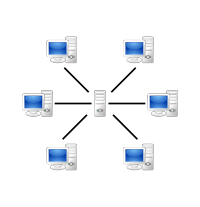
Client-server describes the relationship between two computer programs in which one program, the client program, makes a service request to another, the server program. Standard networked functions such as email exchange, web access and database access, are based on the client-server model. For example, a web browser is a client program at the user computer that may access information at any web server in the world. To check your bank account from your computer, a web browser client program in your computer forwards your request to a web server program at the bank. That program may in turn forward the request to its own database client program that sends a request to a database server at another bank computer to retrieve your account balance. The balance is returned to the bank database client, which in turn serves it back to the web browser client in your personal computer, which displays the information for you.
The client-server model has become one of the central ideas of network computing. Most business applications being written today use the client-server model. So do the Internet's main application protocols, such as HTTP (Hypertext Transfer Protocol), SMTP (Simple Mail Transfer Protocol), Telnet, and DNS (Domain Name System), among others.
Specific types of clients include web browsers, email clients, and online chat clients.
Specific types of servers include web servers, FTP (File Transfer Protocol) servers, application servers, database servers, mail servers, file servers, and print servers..
A virtual private network (VPN) is a technology that creates a safe and encrypted connection over a less secure network, such as the internet. VPN technology was developed as a way to allow remote users and branch offices to securely access corporate applications and other resources. To ensure safety, data travels through secure tunnels and VPN users must use authentication methods -- including passwords, tokens and other unique identification methods -- to gain access to the VPN.
A virtual LAN, commonly known as a VLAN, is a group of hosts with a common set of requirements that communicate as if they were attached to the same broadcast domain, regardless of their physical location. A VLAN has the same attributes as a physical Local Area Network, but it allows for end stations to be grouped together even if they are not located on the same network switch. Network reconfiguration can be done through software instead of physically relocating devices. See Objective 3.3: Advanced Switching for more information on the functions of VLANs.
