OpenSCAD User Manual/STL Import and Export
A prime ingredient of any 3D design flow is the ability to import from and export to other tools. The STL file format is currently the most common format used.
Importing is achieved by the import() command.
[Note: Requires version 2015.03-2] The File >> Open command may be used to insert this command. The file type filter of the Open File dialog may show only OpenSCAD files, but file name can be replaced with a wildcard (e.g. *.stl) to browse to additional file types.
import
[edit | edit source]Imports a file for use in the current OpenSCAD model. The file extension is used to determine which type.
- 3D geometry formats
- STL (both ASCII and Binary)
- OFF
- OBJ
- AMF (deprecated)
- 3MF
- 2D geometry formats
- DXF
- SVG
- Data formats
- JSON [Note: Requires version Development snapshot]
- Other
- CSG can be imported using include<> or loaded like an SCAD file
- PNG can be imported using surface()
Parameters
[edit | edit source]- <file>
- A string containing the path to file.:If the give path is not absolute, it is resolved relative to the importing script. Note that when using
include<>with a script that usesimport(), this is relative to the script doing theinclude<>. - <center>
- Boolean. If true, the center of the object is placed at the origin. [Note: Requires version Development snapshot]
- <convexity>
- An Integer. The convexity parameter specifies the maximum number of front sides (or back sides) a ray intersecting the object might penetrate. This parameter is needed only for correctly displaying the object in OpenCSG preview mode and has no effect on the polyhedron rendering. Optional.
- <id>
- String. For SVG import only, the id of an element or group to import. Optional. [Note: Requires version Development snapshot]
- <layer>
- For DXF and SVG import only, specify a specific layer to import. Optional.
- $fn
- Double. The number of polygon segments to use when converting circles, arcs, and curves to polygons. [Note: Requires version Development snapshot]
- $fa
- Double. The minimum angle step to use when converting circles and arcs to polygons. [Note: Requires version Development snapshot]
- $fs
- Double. The minimum segment length to use when converting circles and arcs to polygons. [Note: Requires version Development snapshot]:
import("example012.stl", convexity=3);
import("D:/Documents and Settings/User/My Documents/Gear.stl", convexity=3);
(Windows users must "escape" the backslashes by writing them doubled, or replace the backslashes with forward slashes.)
data = import("data.json"); // for data formats the file content is assigned to a variable
Read a layer of a 2D DXF file and create a 3D shape.
linear_extrude(height = 5, center = true, convexity = 10)
		import_dxf(file = "example009.dxf", layer = "plate");
Convexity
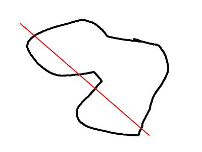
[edit | edit source]This image shows a 2D shape with a convexity of 2, as the ray indicated in red intersects with the 2D shape in at most two sections. The convexity of a 3D shape would be determined in a similar way. Setting it to 10 should work fine for most cases.
Notes
[edit | edit source]In the latest version of OpenSCAD, import() is now used for importing both 2D (DXF for extrusion) and 3D (STL) files.
CGAL ERROR: assertion violation!
[edit | edit source]If you want to render the imported STL file later, you have to make sure that the STL file is "clean". This means that the mesh has to be manifold and should not contain holes nor self-intersections. If the STL is not clean, it might initially import and preview fine, but then as soon as you attempt to perform computational geometry on it by rendering a combination of it with something else, you might get warnings about it not being manifold, your imported stl might disappear from the output entirely, or you might get errors like:
 CGAL error in CGAL_Build_PolySet: CGAL ERROR: assertion violation!
 Expr: check_protocoll == 0
 File: /home/don/openscad_deps/mxe/usr/i686-pc-mingw32/include/CGAL/Polyhedron_incremental_builder_3.h
 Line: 199
or
 CGAL error in CGAL_Nef_polyhedron3(): CGAL ERROR: assertion violation!
 Expr: pe_prev->is_border() || !internal::Plane_constructor<Plane>::get_plane(pe_prev->facet(),pe_prev->facet()->plane()).is_degenerate()
 File: /home/don/openscad_deps/mxe/usr/i686-pc-mingw32/include/CGAL/Nef_3/polyhedron_3_to_nef_3.h
 Line: 253
In order to clean the STL file, you have the following options:
- use http://wiki.netfabb.com/Semi-Automatic_Repair_Options to repair the holes but not the self-intersections.
- use netfabb basic. This free software doesn't have the option to close holes nor can it fix the self-intersections.
- use MeshLab, This free software can fix all the issues.
Using MeshLab, you can do:
- Render - Show non Manif Edges
- Render - Show non Manif Vertices
- if found, use Filters - Selection - Select non Manifold Edges or Select non Manifold Vertices - Apply - Close. Then click button 'Delete the current set of selected vertices...' or check http://www.youtube.com/watch?v=oDx0Tgy0UHo for an instruction video. The screen should show "0 non manifold edges", "0 non manifold vertices"
Next, you can click the icon 'Fill Hole', select all the holes and click Fill and then Accept. You might have to redo this action a few times.
Use File - Export Mesh to save the STL.
If Meshlab can't fill the last hole then Blender might help:
- Start Blender
- `X, 1` to remove the default object
- File, Import, Stl
- `Tab` to edit the mesh
- `A` to de-select all vertices
- `Alt+Ctrl+Shift+M` to select all non-manifold vertices
- `MMB` to rotate, `Shift+MMB` to pan, `wheel` to zoom
- `C` for "circle" select, `Esc` to finish
- `Alt+M, 1` to merge or `Space` and search for "merge" as alternative
- Merging vertices is a useful way of filling holes where the vertices are so closely packed that the slight change in geometry is unimportant compared to the precision of a typical 3D printer
Importing JSON
[edit | edit source]This requires enabling import-function feature in development build. If you import a file with the suffix "json" or "csv", import returns a JSON-object datatype which there is not a way to express as a literal value -- it can only be imported.
Note: Files with the ".csv" file suffix are also treated as JSON files, though these formats are not the same -- a CSV file saved from a spreadsheet program cannot be used here.
/* input file contains:

{"people":[{"name":"Helen", "age":19}, {"name":"Chris", "age":32}]}
*/
t = import("people.json");
echo(t);
people = t.people;
for(i=[0:len(people)-1]) {
	person = people[i];
	echo(str(person.name, ": ", person.age));
}
Which results in this output:
ECHO: { people = [{ age = 19; name = "Helen"; }, { age = 32; name = "Chris"; }]; }
ECHO: "Helen: 19"
ECHO: "Chris: 32"
import_dxf
[edit | edit source][Deprecated: import_dxf() will be removed in future releases. Use import() instead.]
Read a DXF file and create a 3D shape.
linear_extrude(height = 5, center = true, convexity = 10)
		import_dxf(file = "example009.dxf", layer = "plate");
import_stl
[edit | edit source][Deprecated: import_stl() will be removed in future releases. Use import() instead. See above.]
Imports an STL file for use in the current OpenSCAD model
import_stl("body.stl", convexity = 5);
surface
[edit | edit source]surface() reads Heightmap information from text or image files.
It can read PNG files.
Parameters
[edit | edit source]- file
- String. The path to the file containing the heightmap data.
- center
- Boolean. This determines the positioning of the generated object. If true, object is centered in X- and Y-axis. Otherwise, the object is placed in the positive quadrant. Defaults to false.
- invert
- Boolean. Inverts how the color values of imported images are translated into height values. This has no effect when importing text data files. Defaults to false. [Note: Requires version 2015.03]
- convexity
- Integer. The convexity parameter specifies the maximum number of front sides (back sides) a ray intersecting the object might penetrate. This parameter is needed only for correct display of the object in OpenCSG preview mode and has no effect on the final rendering.
Text file format
[edit | edit source]The format for text based heightmaps is a matrix of numbers that represent the height for a specific point. Rows are mapped to the Y-axis, columns to the X axis. The numbers must be separated by spaces or tabs. Empty lines and lines starting with a # character are ignored.
Images
[edit | edit source][Note: Requires version 2015.03]
Currently only PNG images are supported. Alpha channel information of the image is ignored and the height for the pixel is determined by converting the color value to Grayscale using the linear luminance for the sRGB color space (Y = 0.2126R + 0.7152G + 0.0722B). The gray scale values are scaled to be in the range 0 to 100.
Examples
[edit | edit source]Example 1:
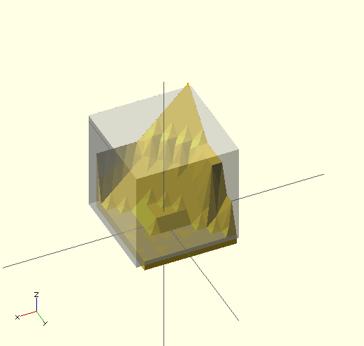
//surface.scad
surface(file = "surface.dat", center = true, convexity = 5);
%translate([0,0,5])cube([10,10,10], center =true);
#surface.dat
10 9 8 7 6 5 5 5 5 5
9 8 7 6 6 4 3 2 1 0
8 7 6 6 4 3 2 1 0 0
7 6 6 4 3 2 1 0 0 0
6 6 4 3 2 1 1 0 0 0
6 6 3 2 1 1 1 0 0 0
6 6 2 1 1 1 1 0 0 0
6 6 1 0 0 0 0 0 0 0
3 1 0 0 0 0 0 0 0 0
3 0 0 0 0 0 0 0 0 0
Result:
Example 2
 // example010.dat generated using octave:
 // d = (sin(1:0.2:10)' * cos(1:0.2:10)) * 10;
 // save("example010.dat", "d");
 intersection() {
   surface(file = "example010.dat", center = true, convexity = 5);
   rotate(45, [0, 0, 1]) surface(file = "example010.dat", center = true, convexity = 5);
 }
Example 3:
[Note: Requires version 2015.03]
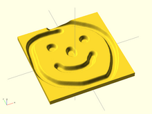
// Example 3a
scale([1, 1, 0.1])
  surface(file = "smiley.png", center = true);
// Example 3b
scale([1, 1, 0.1])
  surface(file = "smiley.png", center = true, invert = true);
Export
[edit | edit source]After rendering with F6, the "File --> Export" menu can be used to export as STL, OFF, AMF, 3MF, DXF, SVG, CSG, PNG (image), or PDF.
Be sure to check the console window for error messages.
- STL, OFF and DXF are imported using
import() - CSG can be imported using
include<>or loaded like an SCAD file - PNG can be imported using
surface() - There are open pull requests for SVG and AMF, which require a bit more work/testing
- The file suffix is used to determine type
STL Export
[edit | edit source]To export your design, select "Export as STL..." from the "File --> Export" menu, then enter a filename in the ensuing dialog box. Don't forget to add the ".stl" extension.
Trouble shooting:
After compile and render CGAL (F6), you may see that your design is simple: no. That's bad news.
See line 8 in the following output from OpenSCAD 2010.02:
Parsing design (AST generation)...
Compiling design (CSG Tree generation)...
Compilation finished.
Rendering Polygon Mesh using CGAL...
Number of vertices currently in CGAL cache: 732
Number of objects currently in CGAL cache: 12
   Top level object is a 3D object:
   Simple:         no                <*****************
   Valid:         yes
   Vertices:       22
   Halfedges:      70
   Edges:          35
   Halffacets:     32
   Facets:         16
   Volumes:         2
Total rendering time: 0 hours, 0 minutes, 0 seconds
Rendering finished.
When you try to export this to .STL, this message appears:
Object isn't a valid 2-manifold! Modify your design..
"Manifold" means that it is "water tight" and that there are no holes in the geometry. In a valid 2-manifold each edge must connect exactly two facets. That means that the program must be able to connect a face with an object. E.g. if you use a cube of height 10 to carve out something from a wider cube of height 10, it is not clear to which cube the top or the bottom belongs. So make the small extracting cube a bit "longer" (or "shorter"):
difference() {
	// original
	cube (size = [2,2,2]);
	// object that carves out
	# translate ([0.5,0.5,-0.5]) {
	    cube (size = [1,1,3]);
	}
}

Here is a more tricky little example taken from the OpenSCAD Forum (retrieved 15:13, 22 March 2010 (UTC)):
module example1() {
		cube([20, 20, 20]);
		translate([-20, -20, 0]) cube([20, 20, 20]);
		cube([50, 50, 5], center = true);
	}
module example2() {
		cube([20.1, 20.1, 20]);
		translate([-20, -20, 0]) cube([20.1, 20.1, 20]);
		cube([50, 50, 5], center = true);
	}
Example1 would render like this:

The example1 module is not a valid 2-manifold because both cubes are sharing one edge. They touch each other but do not intersect.
Example2 is a valid 2-manifold because there is an intersection. Now the construct meets the 2-manifold constraint stipulating that each edge must connect exactly two facets.
Pieces you are subtracting must extend past the original part. (OpenSCAD Tip: Manifold Space and Time, retrieved 18:40, 22 March 2010 (UTC)).
For reference, another situation that causes the design to be non-exportable is when two faces that are each the result of a subtraction touch. Then the error message comes up.
difference () {
   cube ([20,10,10]);
   translate ([10,0,0]) cube (10);
}
difference () {
   cube ([20,10,10]);
   cube (10);
}
simply touching surfaces is correctly handled.
translate ([10,0,0]) cube (10);
cube (10);


