SAASTE Technology/Activities/Electronic Circuits
Electrical System
Grade 9
Electronics
[edit | edit source]You will need the following component / Parts
Resistors (all ¼ Watt 5% carbon)
- R1 - 680 Ohm
- R2 - 4,7 K Ohm
- R3 - 2,7 M Ohm (for activity 4)
Semiconductor
- Q1 - BC337 (or equivalent)
- LED 1- 5mm
- LED 2 - 5mm infra red detector
- LED (for activity 4)
A Resistor Colour Code Chart is available on the last page of this document.
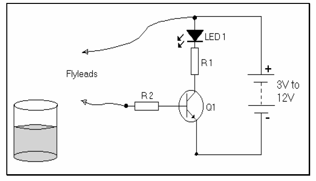
Connect / build the circuit shown in the diagram below:
Note: The fly lead is simply a short length (approx. 10cm) of conductive wire (with both ends stripped of insulation)
Activity 1:
[edit | edit source]Attach the loose end of the fly lead to the negative (-) side of the battery and observe the output.
Now remove the fly lead and attach to the positive (+) side of the output and observe the output.
Activity 2:
[edit | edit source]Disconnect the fly lead from the battery. Touch the end of the fly lead with your bare fingers.
What do you observe?
- ...........................................................................................................
- ............................................................................................................
Activity 3:
[edit | edit source]Connect another fly lead as shown in the circuit diagram below:

Insert both fly leads into a beaker containing water and observe the output.
Activity 4:
[edit | edit source]Use your original circuit and extend it by connecting LED 2 and R3 as shown in the circuit diagram below:
LED 2 - 5mm. infra red detector LED R 3 - 2,7 MΩ
Use any remote control (from a TV, Hi-Fi etc.). Bring it close to LED 2. Press any button on the remote control and observe the output.
Note: An LED is a transducer: it converts energy from one form to another
Component data:
- R1 - Blue, grey, brown, gold
- R2 - Yellow, violet, red, gold
- R3 - Red, violet, green, gold
Note: 5%(gold), 10%(silver) or 20%(no 4th band) resistors may be used
The colours for the 4, 7 KΩ resistor was worked out like this: Each number of the value of the resistor correspond to the three bands on the one end of the resistor.
4 in the first band = yellow 7 in the second band = violet K in the third band would be orange. Because there is a decimal place (comma) between the 4 & 7, we move one decimal place and now have 2 zeros which correspond to red.
Try working out the colours for the following resistors: 47 KΩ, 50Ω, 330Ω , 100Ω , 560Ω , 390Ω.
Semiconductors:
Transistor Q1: BC 337:
B-Base; C-Collector; E-Emitter
Glossary=
[edit | edit source]Resistor: An electronic component which slows or reduces the current and/or creates a voltage drop
L.E.D. (Light Emitting Diode): A special diode which emits light when a current flows through it.
Transistor: An electronic component which may be used as a switch or as an amplifier. They are broadly divided into PNP and NPN (the BC 337 used above is an NPN transistor)
Infra-red: A narrow band of the light spectrum invisible to the naked eye.
Anode: Positive
Cathode: Negative
Author: Ricardo Miller
Contributions by Osman Sadeck
Editor: Osman Sadeck
