Wikijunior:Raspberry Pi/Raspberry Pi Simon Says Game
| This tutorial is being developed and is untested. |

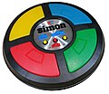
Simon Says (or just simply Simon) is an electronic board game where the object is to memorise the sequence of red, yellow, blue and green colours and then press the corresponding buttons in order.
Components
[edit | edit source]Breadboard
[edit | edit source]
The mini breadboard has a top and bottom section. All the points along each column in each section are joined, so we can make electrical connections.
You will need ×1 breadboard.
Light-Emitting Diode (LED)
[edit | edit source]| LEDs always need to be connected with a resistor. If you connect them without a resistor, they will burn out and probably won't work again. |

The LED (Light-Emitting Diode) has a short leg and a long leg. If you feel around the rim, you'll also find a flat edge. The short leg and flat edge always connect to the negative (ground).
You will need ×4 LEDs: ×1 red, ×1 blue, ×1 green and ×1 yellow.
Resistor
[edit | edit source]
The resistor can be connected any way around. We're using a 270 Ohm resistor but anything between 220–470 Ohms will work fine.
You will need ×4 resistors.
Momentary switch
[edit | edit source]
The switch can be connected any way around. When pressed, it allows electricity to flow; when released, the electricity stops. This kind of push-button is known as a "momentary press-to-make switch".
You will need ×4 momentary switches.
Jumper wires
[edit | edit source]
Jumper wires (also called DuPont wires) connect electronic components to the GPIO pins. You should also have two short and one long jumper wire (all "female to female" – holes at both ends).
You will need ×16 jumper wires.
Putting the breadboard together:
[edit | edit source]| The colour of the wires is not important – where you put the wires is VERY important! Each of the holes on the breadboard is numbered – make sure everything goes in the correct hole. |

The Raspberry Pi has two ways of labelling the General Purpose Input-Output (GPIO) pins:
- Board numbering – just starts from the bottom-left at 1, and works its way up and right, through to 40.
- BCM numbering (Broadcom numbering) – is the way the Raspberry Pi's processor sees the pin connections.
Step 1: Connect the LEDs to the GPIO pins on the Raspberry Pi. You can use any combination of GPIO pins, but it is important to note that the LEDs must be connected to pins that support PWM (pulse-width modulation).
| Component | GPIO pin |
|---|---|
| Red LED | pin 17 (GPIO 17) |
| Blue LED | pin 27 (GPIO 27) |
| Yellow LED | pin 22 (GPIO 22) |
| Green LED | pin 23 (GPIO 23) |
Step 2: Connect the buttons to the GPIO pins on the Raspberry Pi. You can use any combination of GPIO pins, but it is important to note that the buttons must be connected to pins that support input.
| Component | GPIO pin |
|---|---|
| Button | pin 5 (GPIO 5) |
| Button | pin 6 (GPIO 6) |
| Button | pin 13 (GPIO 13) |
| Button | pin 19 (GPIO 19) |
Write a Python program:
[edit | edit source]Step 3: Write a Python program to control the LEDs and buttons. The program should generate a random sequence of LEDs to light up, and then wait for the user to press the corresponding buttons in the correct sequence. If the user presses the buttons correctly, the program should advance to the next level. If the user presses the wrong button, the program should end the game.
Once you have written the Python program, you can save it as a file with a `.py` extension, such as `simon_says.py`. Then, you can run the program by typing the following command into a terminal window:
python simon_says.py
The game will start and the LEDs will light up in a random sequence. Press the corresponding buttons in the correct sequence to advance to the next level. If you press the wrong button, the game will end.
You can make the game more challenging by increasing the length of the sequences and by adding different types of actions, such as clapping your hands or stomping your feet. You can also add sound effects to the game using a buzzer or speaker.
Files:
[edit | edit source]A Piano Note MIDI.mid.mp3
[edit | edit source] |
|
| Problems listening to this file? See media help. | |
C Piano Note MIDI.mid.mp3
[edit | edit source] |
|
| Problems listening to this file? See media help. | |
simon-says.py
[edit | edit source]import RPi.GPIO as GPIO
import random
# Define the GPIO pins for the LEDs and buttons
led_pins = [17, 27, 22, 23]
button_pins = [5, 6, 13, 19]
# Set up the GPIO pins
GPIO.setmode(GPIO.BCM)
for pin in led_pins:
GPIO.setup(pin, GPIO.OUT)
for pin in button_pins:
GPIO.setup(pin, GPIO.IN)
# Define a function to light up an LED
def light_led(pin):
GPIO.output(pin, GPIO.HIGH)
# Define a function to turn off an LED
def turn_off_led(pin):
GPIO.output(pin, GPIO.LOW)
# Define a function to generate a random sequence of LEDs
def generate_random_sequence():
sequence = []
for i in range(4):
sequence.append(random.randint(0, 3))
return sequence
# Define a function to check if the user pressed the buttons in the correct sequence
def check_user_input(sequence):
for i in range(len(sequence)):
if GPIO.input(button_pins[sequence[i]]) == False:
return False
return True
# Start the game
sequence = generate_random_sequence()
# Light up the LEDs in the sequence
for i in range(len(sequence)):
light_led(led_pins[sequence[i]])
time.sleep(0.5)
turn_off_led(led_pins[sequence[i]])
# Wait for the user to press the buttons in the sequence
while True:
if check_user_input(sequence):
# The user pressed the buttons correctly
sequence += generate_random_sequence()
else:
# The user pressed the wrong button
print("Game over!")
break
# Clean up the GPIO pins
GPIO.cleanup()
