Blender 3D: Noob to Pro/Simple Vehicle: Body
|
|
Applicable Blender version: 2.75. |
Techniques
[edit | edit source]You should already know how to:
- Make a mesh
- Navigate the viewport
- Extrusion
- Form faces
- Name objects
This section will recap and introduce:
- Deleting and creating edges
- Subdividing
- Merging vertices
- Loop subdivide
- Adding unconnected vertices in one object
Planning
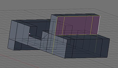
[edit | edit source]The jeep is being designed to include the back, flatbed, door holes, dashboard, window, and hood. The window is extruded straight up (older jeeps' windshields aren't slanted), and I decided to add a lower back to later hold the bumper/lights if you want to add them.
Building the Jeep
[edit | edit source]Extrude the Chassis
[edit | edit source]Start a new file.
Change to front view ( NUM1 ), switch to EDIT mode, and deselect all ( A ).

Be in Face select mode
Starting from the default cube (#1), box select ( B ) on the right edge to select the right face, and extrude ( E ) 2 units (#2) to the right along the X axis (should default, otherwise X ). Continue with three more extrusions to the right along the X axis of 1 unit (#3), 1 unit (#4), and 2 units (#5).
deselect all ( A ).
Now starting again from the default cube (#1), box select ( B ) on the left edge to select the left side face, and extrude 1 unit (#6) to the left in the X axis
deselect all ( A ).
box select ( B ) on the bottom edge of block #6 to select the bottom face, and extrude 1 unit (#7) down in the Z axis.
deselect all ( A ).
Finally box select ( B ) on the top edge of #4 the second block from the right to select the top face, and extrude up 2 units (#8) in the Z direction.
Widen the chassis
[edit | edit source]
Now to widen the jeep body.
Switch to top view ( NUM7 ).
deselect all ( A ).
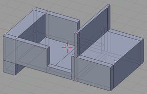
set "Limit selection to visible" off Increase the width of the existing boxes (#1) with one square (#2) by box selecting ( B ) everything (since you're in face select mode it will select all the faces of the starting chassis), now Scale ( S ) 2 times on the Y axis ( Y )
And select all faces on one side and extrude along the Y Axis 1 unit. do the same on the other side
This should give you the figure that is shown to the right.
Noob note: holding CTRL as you do the above moves and extrusions will lock it to grid steps
Noob note: You might want to save your job here and rename it before carrying on as the options below are easier if you can revisit this stage.

Flatbed and Doors
[edit | edit source]Our jeep design will have somewhat of a cheat - no actual door.
There are now a few different ways of doing this (thanks to reader submissions)! Try each one and study the results, as they will teach you about the issues you will encounter when you start making models of your own design;
Method 1 is the simplest of them, but teaches you the least in dealing with mesh trouble.
Method 1
[edit | edit source]Make the jeep bed
[edit | edit source]
In NUM7 view
Be in Face select mode
Turn occlude background geometry (now called Limit selection to visible) on. It's the button with the spotty-box icon to the right of vertex, edge, and face select buttons.
Select ( RMB , then SHIFT + RMB ) the top faces where the flatbed and then doors should go. You should now have four faces selected, two large ones for the bed, and two small ones for the doors.

Extrude ( E ) the "region" -2, on the Z axis ( Z ).
Make the no-door holes
[edit | edit source]

Now in front view ( NUM1 )
Be in Edge select mode
Select ( RMB ) the top edge of the door face, and delete ( X ) the "edge". Next, do the same to the corresponding door edge on the other side.

Be in Face select mode
Select the faces in the bottom of the door wells, and extrude them up 0.5 along the Z axis.

Select the bed panels, and extrude them up .1 along the Z axis ( leaving them on top of each other will cause problems with rendering engines down the road )

Noob Note: Be very careful as you extrude the parts up, since they are on top of each other, it's easy to select the face on the outside, rather than the one on the inside. Once you've done the extrusion, check the normal lines by hitting the draw normals button in the mesh tools more panel (if you can't see it, hover and scroll with the MMB). If you don't get good normals, then hit undo, then reselect the faces, and try again until you get the correct face being extruded (50% chance of getting the wrong face pulled up). Or select the faces with a wrong normal and hit the Flip Normals button in the Mesh Tools tab.
Finally, select the whole body and remove doubles, ( A ) to select all then ( W ) to bring up the specials menu. On the special's menu, hit "remove doubles".
Note: removing doubles every couple of steps is a good habit to get into, and will save you time down the road.
Method 2
[edit | edit source]Make the jeep bed
[edit | edit source]
be in Top view ( NUM7 ), and Face select Mode.
Select the two faces in between the bumpers and windshield ( RMB , then SHIFT + RMB ).
Now delete both faces ( X ->"faces").
Note: you could also be in edge select mode, and delete (xkey) the edge between the two faces, for the same end result.

You will now add outer faces around the hole we just opened in the model, by selecting two vertices at the top of the model, and two from the bottom of the model.
Be in vertex mode
Deselect all ( A twice)
Starting at vertex A, circle select ( C ) vertex B, C, and D,

Next create a face ( F ); do this same procedure 5 more times at the vertx groups show in the pictures.


Issues with exposed inside faces (Normals)
[edit | edit source]
Now that we have gotten the new outer faces in place we can't see into the model any more but we still have a big problem, the floor is actually the outside face of the bottom of the model, this is not good because you should never leave exposed inside faces (the other side of outer faces) on a model.
Exposed inside faces are invisible when looking through them when you apply textures and render it, since nearly all rendering engines completely ignore inside faces ( A common problem with many sketchup models, ah the irony! ).
You can tell a face is an inside face, by the fact that if you turn on show normals, and show vnormals, on the mesh tools more panel, the outside faces and vertices will have blue lines shooting out of them, while inside faces will not.
Understanding this now will save you lots of wasted hours in the future trying to fix your normals.

Press NKEY and go to "mesh display" and click on the cube with the face highlighted. Look closely at the exposed interior faces in the floor of the truck bed, they don't have blue lines popping out in the inside, only on the outsides.
Now select textured from the box where you pick wireframe, or shaded, and the exposed inside faces will become invisible when viewed from the inside, but look great when looked at from the outside.
In newer versions it is no longer invisible, and it seems to work but it still has no normals, and it is still important to know.
Add the floor of the bed
[edit | edit source]Lets make a floor for the bed now.

Be in Face select mode
Select ( RMB ) both faces of the truck bed,
Extrude ( E ) pick "region" from the popup, and move up along the Z axis ( Z ), by about 0.2.
With the two faces selected, hit mesh -> normals -> flip to make their normals correct for their new position
Now rotate the model till you're looking at it from the bottom, as you can see there is now a hole that needs some extra inside faces removed, and new faces added to compete the bottom.

Select each extra face on the sides, and delete ( X ) the "faces" as shown in the photos.

Change to Vertex select mode
Select ( RMB ) corners a, b, c, d, and create a face F , then do the same for c, d, e, and f.

Recheck the normals, and make sure you only have outer faces on the outside of your model.
Make the door holes
[edit | edit source]Method 2.2 is easier!
Method 2.1 Subdivision
[edit | edit source]
To cut out one door, select the four vertical edges where the door will go.

Use the subdivide command ( W ) to cut the edges in half. You'll notice that the subdividing will also affect the adjoining faces.

Select the two edges at the top of the door panel and delete them, removing the top half of it.

Change to Vertex select mode
Now build up faces by selecting the groups of vertex's as shown in the photo, and creating a face ( F ). Do the same thing for the other side, removing/adding edges and creating new faces.

If you want to clean up the look of the sub divided faces in the model
Change to Face select mode, and select the faces that are going to be combined.
Press F and a little window will appear titled 'Make Faces'. Click on 'Make FGon' to merge the faces. (As you may have guessed, if an FGon face is created and you want to later undo it, select the 'clear FGon' option in the Make Faces window.)
Note: to merge an Fgon to a flat face, select it and hit CTRL + J
Pro Note: You don't even have to make an FGon. Just select the door-to-be, Tris and Quads both, and hit CTRL + J .
Noob Note: Q. What is an FGon??
A. It is a fake polygon, a way to hide triangles and quads on flat faces.
Method 2.2 Multicut
[edit | edit source]
Be in frontview (NUM1).
Select the top edges where you want the doors
Multicut (KKEY), enter two in the popup, draw a line along the axis of the cut, as shown in the photo, and hit ENTER .

Then move the newly created edges down and towards the sides.
method 2.3 (Noobie)
[edit | edit source]Select top face of where door is going to be
    E  to extrude, pick "Region" from the popup menu
    Z  to lock in Z direction
   hold CTRL to snap to whole BUs and move down one BU
Select 2 top edges that look like they have no widths
X to erase, pick "Edges" from the popup menu
Two faces will be missing. For each individual missing face, Select top and bottom edges
F to fill in the missing face.
Resizing the bed and windshield
[edit | edit source]Go ahead and resize the widths of the bed and windshield.
As a precaution, Remove doubles before starting!

To narrow the width of the window, change to Edge mode and select the edges shown in the picture, then move ( G ) along the X axis.

To narrow the width of the side, change to Edge mode and select the edges shown in the picture, then move ( G ) along the Y axis.

Always move as many vertices or edges at the same time to not only work faster but to make sure they are moved equally. The use of circle select, loop select, and SHIFT while moving vertices is very helpful in fine movements.

If you want an object to come to a point such as a wedge from a cube, merge vertices.
In this example, the lower back area will be modified. Select two vertices to join together and press ALT + M . Select the option for your merging. 'At First' or 'At Last' will probably be the option that will work here.
Play around to see what each merge option does. After the merging, Blender will tell you how many vertices were removed.
Be certain to "remove doubles" ( W ), as merging creates lots of them. ( You can also find it on the menu Mesh ==> Vertices ==> Remove doubles)

Extrude the bed surface upward. This is only useful in hiding the tires that we'll add later in the tutorial. Alternatively, you could make two boxes to hide them.
A Touch of Detail
[edit | edit source]Adding an Engine Hood
[edit | edit source]Method 1
[edit | edit source]
Let's add some detail to the model - how about the hood? First thing to do is add some edges to the front of the jeep. Press CTRL + R to enter Loop Subdivide. A pink loop will appear around the mesh. Put the cursor over the area to get the example picture to appear.

When the loop is in the right place, LMB click. The place to put the actual cut can now be selected. Do this twice - once for each side. Move and align the resulting edges to form an angle to the front and bring the window vertices in.
Extrude the hood surface up a small amount. We don't want it too high, just high enough to catch the light.
Zoom in and select the top-front hood edge created from the extrusion. Drag it out along the X axis. Select the now diagonal face of the hood extrusion. Extrude from it. The result will come out of the surface at a diagonal angle. Take the resulting vertices and move them close to the front of the jeep.

Using the additional lines from the loop subdivide you can improve the shape of the window
Method 2
[edit | edit source]Another way to raise the Jeep hood. It doesn’t require loop cuts, so is a bit simpler.

Step 1. Make Inner Square.
Switch to Top-view ( NUM7 ), or slightly rotated off for easier viewing.
Face-select the top square of the hood.
Do E -xtrude, then hit <esc>. NOTE: this WILL make a new surface, hitting ESC doesn’t cancel the extrude, just makes its location to be exactly on the old surface.
Do S -cale and type 0.9 and hit <return>. Now you will see the new surface as a smaller square (or really rectangle) on top of the jeep hood square.
Noob Note: What I had to do is S -cale on Z and type 0.9, otherwise the New Surface For the hood would end up shooting through the Windshield.

Step 2. Shape Hood.
Still in Top-view NUM 7, deselect all.
Box-select the right two vertices of the new square, towards the front of the jeep.
Do S -cale on Y, and type 0.8 and hit <return>. Leave the two vertices still selected.
Do G -rab on X, and type 0.2 and hit <return>.
Face-select the resulting quadrilateral.
Switch to Side-view NUM 3.
Do E -xtrude on Z and type 0.2 and hit <return>. I used 0.2 to exaggerate the screenshot a bit, you probably want 0.1 instead.
Now you should have a raised hood on the front of the jeep.
Method 3
[edit | edit source]Another way to extruding the Hood of the jeep including a lip that comes over the front.

Step 1: In face select mode ( CTRL + TAB ->faces), select the top of the hood and press E to extrude it. Only extrude it a small amount.

Step 2: Staying in Face select mode, here is the tricky part. Select the small face on the front of the hood you just extruded. Then, hit E then ESC . This creates a duplicated face on top of the one you selected. Do not click or move the mouse between these two keystrokes.

Step 3: Now deselect the selected face by hitting AKEY. Then enter Edge select mode ( CTRL + TAB ->edges) and select the top edge of the face you just deselected.

Step 4: Hit NUM1 to go to the side view. Now using the red X arrow pull the edge out a little further than you pulled up the hood itself then hit LMB .

Step 5: Now rotate just enough so you can see under the wedge you just made. Go back into Face select mode ( CTRL + TAB ->faces) and select the face on the underside of it.

Step 6: Go back into side view with NUM1 . Now hit E to extrude the face a little with the mouse. When it's a good size hit LMB .

Step 7: Now make sure the "Select only visible" button is turned off ("Occlude background geometry" in later versions) and go into Vertex select mode ( CTRL + TAB ->vertices). Play around with the vertices pulling them a little closer to the front of the jeep. It's best to select using the box select ( B ) or the Lasso ( CTRL + LMB ).

The end result should be an extruded hood with a lip.
Add a Fender
[edit | edit source]
In the topdown view ( NUM7 ), add a plane. Extrude an edge twice to result in three connected planes.

Pull the sides down to form a trapezoid shape and reduce the width.

Once it is in the desired shape, select the three faces and duplicate it. Press SHIFT + D and all selected vertices, edges, and/or faces will be duplicated. The copy will automatically be grabbed for moving.
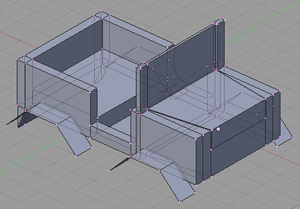
Move the duplicate to the jeep body and repeat the duplication two more times for a total of four fenders.
Noob note: A good idea is to first position one fender, then copy it and restrict movement to x or y-axis. Then copy both fenders and move the two new copies along x or y-axis. Much simpler than trying to position four fenders individually.
Add a rocket launcher mount
[edit | edit source]
We'll move on to making a tripod support for the rocket launcher.
Add a cylinder mesh with 12 vertices then scale and size it so that it looks like a tube. Once you have it to a size you like,
Duplicate it twice for a total of 3 cylinders.
Rotate two of the cylinders in the NUM1 view by LMB clicking on the white circle that appears when the cylinder is selected in rotate mode.
The picture on the left is an example of the end result.

Change to overhead view ( NUM7 ) and put together the three cylinders so the tops come close together. Now all three can be selected and moved or rotated accordingly.

Move the tripod onto the jeep flat bed. The final steps are to select your materials and rename the object (described in the wheel section). This will complete our simple jeep model.
Subsurf
[edit | edit source]Since we expect a jeep body to have squared up edges, we won't subsurf this part of the model.
Optional Activities
[edit | edit source]Feel free to add anything you see fit such as bumpers, guard rails, doors, steering wheel, lights, etc. You can either have them on the same object or separate objects (useful if you want to move them around).
